CONTENTS
- Introduction
- Operation Principle
- Design Considerations
- Transfer Region
- General Specifications
- Beam Shaper Quality Factor
- Comparison of Top-Hat (TH) and Stable Top-Hat (ST)
- Comparison of Beam Shaper and Polychromatic Beam Shaper
- Typical Tolerances Table for Top Hat Beam Shapers
- Sensitivity to Alignment and Beam Tolerances
- Effects of Tolerances on Beam Shaper
- Beam Shaper Integration Tools
- Beam Shaper Standard Products
- Manual for Using Black Box in Zemax Software
- Beam Shaper Installation Manual
- Download PDF
INTRODUCTION
In various industries there is a need to focus a laser beam to a well-defined size and shape with uniform intensity (flat top). A flat top spot enables uniform laser treatment of the working surface, and maintains the same active area regardless of pulse energy. In addition, the sharp edges of the spot –the narrow “transition region” – create a clear-cut border between treated and untreated zones.
Typical laser applications for a Top Hat shaper include:
- Cutting
- Ablation
- Hole Drilling
- Scribing
- Annealing
- Medical and aesthetic
- Microscopy and science
- Lightsheet cytometry
This application note is meant to contribute to the user’s understanding of the functionality and share considerations that should be taken into account when using a Beam Shaper element.
Operation principle
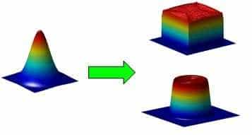
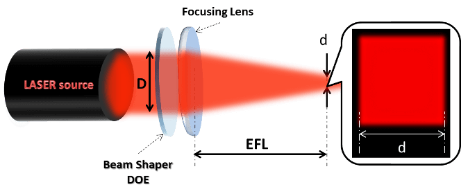
A Top Hat (TH) Beam Shaper is an optical element, mainly based on diffractive technology (Diffractive Optical Element – DOE), and used to transform a Gaussian (TEM00) incident laser beam into a uniform-intensity spot of either round, rectangular, square, line or other custom well defined shapes. The most canonic set-up in the Beam Shaper application consists of a laser, a Beam Shaper element, a focusing optics and a surface to be treated. A typical Set Up with Top Hat beam is shown in fig.1 below.
Figure 1: Typical Set Up
Each beam shaper is designed for use with a specific set of optical system parameters:
- Wavelength
- Input Beam Size (D)
- Output Spot Size (d)
Note: using values of these parameters that are outside of the recommended narrow tolerances will degrade the performance of the Top Hat Beam Shaper element, and possibly render it useless for the application.
Design Considerations
- For good quality beam shaper performance, the laser output should be Single-Mode (TEM00) with an M2 value under 1.3.
- ALL apertures in the beam path must be at least 2x larger than the beam size (1/e2) on the aperture plane (optimally > 2.5x). These often include mirrors (for beam folding or scanning), beam expanders/ telescopes, and focusing optics (lens, objective, F-Theta, etc.).
- All optics in the beam path should be of high quality, i.e. have a low aberrations level, in order not to add wave-front errors which would degrade the beam shaper performance.
- The input beam to be collimated.
- When designing the desired output Top-Hat size, it is important to be familiar with the term “Diffraction Limit (DL)” – this is the physical optical limit of the minimum spot size, i.e the spot size the system optics would give if the beam shaper was removed from the system.
- As a rule of thumb, the beam shaper spot size has to be at least 1.5x times the diffraction-limited spot size as defined in the formula below (for M2 = 1).
The formula for the diffraction-limited spot size:
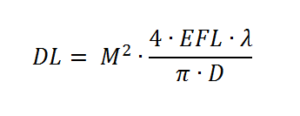
Where: EFL – effective focal length of the focusing optics, λ – wavelength, D – Input Beam Size, M2 – laser beam quality parameter of input laser beam.
Transfer Region
The transfer region is the edge of the top hat, also called the roll off region.
It is defined as the region where the intensity decreases from 90% to 1/e^2.
below is an illustration:
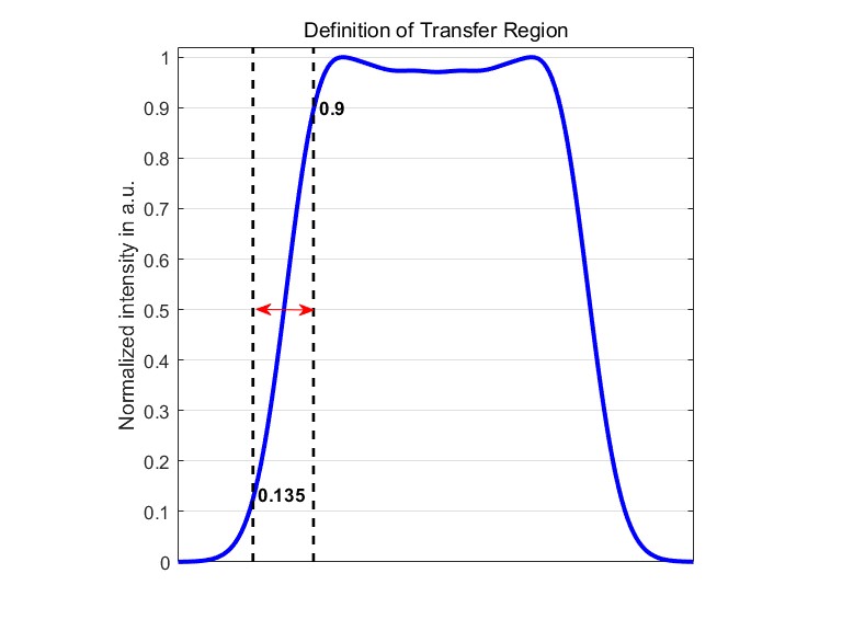
General Specifications
| Materials | Fused Silica, ZnSe, ZnS, Germanium, Silicon, Plastics |
| Wavelength range | 193nm to 10.6um |
| DOE design | 2 – level (binary) to 16 – level, or kinoform (grayscale) |
| Polychromatic design | Continuous free form surface |
| Type | Transmissive or Reflective |
| Minimum Full angle | very small (about 1.5 times Diffraction Limit) |
| Efficiency | Up to 99% |
| Element size | 3 – 150mm |
| Coating (optional) | AR/AR Coating |
| Custom Design | Any Shape |
beam shaper Quality Factor
Some basic rules:
- It is impossible to get a Top Hat size smaller than the diffraction limited spot size (DL).
- The factor between the beam shaper size and the DL defines the quality and efficiency of the beam shaper. A larger factor enables sharper edges.
- The transfer region of the beam shaper can’t be < 0.5 DL size and is generally ~1 DL.
Example of the same top hat size with different DL sizes. As DL size decreases –shaping quality increases, reducing “wasted” energy.
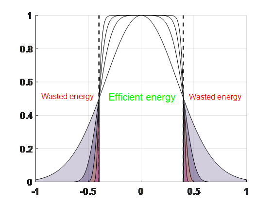
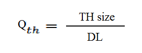
Quality is defined by the ratio of the transfer region to the flat area of the Top hat.
Typically, applications require the transfer region (13.5-90 %) to be as small as possible and the Top Hat profile to have a maximum relative size of flat, uniform area. Thus, the quality (Qth) parameter is defined as:
CoMParison Of TOPHAT (TH) and Stable TopHat (ST) types
Holo/Or uses two different concepts to design beam shapers. For TH elements we use a semi-analytical solution and it’s limited to the basic shapes of line, rectangle, square or round.
ST designs are based on a computer aided numerically optimized design and can be used to achieve any arbitrary shape and intensity distribution profile. TH elements have a larger transfer region, but show better defocus behavior compared to ST element. ST elements have up to twice smaller transfer region compared to equivalent TH elements.
Below is a comparison graph for typical TH/ST with a superposition of equivalent designs – i.e. with the same spot size at 90 %.
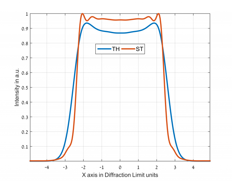
CoMParison Of Beam Shapers And Polychromatic Beam Shapers
The standard Beam Shaper is optimized for a specific wavelength. Other wavelengths will affect the Top Hat performance. If the customer’s application requires a polychromatic source, the polychromatic Beam Bhaper will then normally be a better solution. The polychromatic Beam Shaper works well for a broad wavelength range. However, this product can be less accurate in the Top Hat size and shape.
Below is a table of comparison between standard Beam Shapers and polychromatic Beam Shapers:
| Type | Standard | Polychromatic |
| Wavelength dependence | Yes | No |
| Material | Fused Silica, ZnSe, Plastic | Fused Silica, Germanium |
| Top Hat shape | Any | Round, Square, Line, Rectangle |
| Efficiency | >95% | >95% |
| Uniformity | Typically < 5% | Typically < 10% |
| Top Hat size | Very Precise | Precise |
| Top Hat shape | Very Accurate | Accurate |
| Top Hat shaping quality | Independent of wavelength | inversely proportional to wavelength |
| Top Hat full angle | proportional to wavelength | proportional to refractive index |
The polychromatic Beam Shapers appears in the Beam Shaper product page with format PT-123-A-B-C
Typical Tolerances Table for Top HAt Beam Shapers
| Wavelength deviation from design | ±2 % |
| X-Y displacement (decenter) | ±5% of input beam diameter |
| Tip, Tilt | ±5 degrees |
| Input beam diameter | ±5% |
| Input beam ellipticity | 5% |
| Working distance (defocus) | <50% of the Top Hat spot size at focus |
Sensitivity to Alignment and Beam Tolerances
Beam Shaper elements are sensitive to various parameter tolerances. When one goes about designing a set-up that includes a diffractive optical element (DOE), one should take care to ensure control and stability of these system parameters.
Many of the Top Hat output specifications depend on the relative displacement and/or mismatch of the input beam diameter. Therefore, the system can be made less sensitive by expanding the input beam prior to the design. For example, for an input beam of 10mm diameter, a mismatch of 5% gives 0.5mm tolerance, while for a beam diameter of 2mm, a 5% tolerance corresponds only to 0.1mm.
Effects of Tolerances on beam shaper
The best performance will be obtained for a well-positioned perfectly aligned part, located precisely in the plane of the nominal working distance. To illustrate the sensitivity of Beam Shaper performance to different tolerance parameters, several graphs are included here for a typical Beam Shaper element (WD: 120mm, λ: 532nm, Din: 10mm).
Fig. 4: Effect of x-axis or y-axis de-centering of input beam on Top Hat Profile
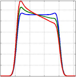
**Noteworthy in figure 4 above is the “tilted” Top Hat profile due to de-centering; i.e. a slope in the intensity going from one side of the spot to the other.
Fig. 5: Effect of Working Plane Defocus on Top Hat Profile
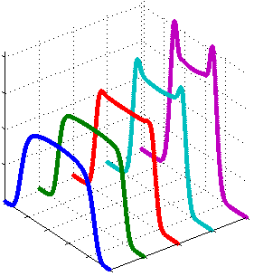
**Note the different behavior of the Top Hat profile when located too close (blue curve) as opposed to being too distant (violet curve). The uniformity suffers a drop in both cases, while the extended distance gives rise to narrow peaks at the Top Hat spot periphery (like “dog ears”), the shorten distance gives a more rounded output.
Fig. 6: Effect of Input Beam Size Tolerance on Top Hat Profile
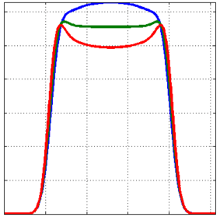
**Interesting to note in fig.6, that this gives a very similar effect as in fig.5. There is a clear parallel between too large beam size and extended defocus. The “dog ears” effect is the same.
Beam Shaper integration toolS
Matlab:
Holo/Or published a Beam Shaper integration tool for MATLAB. This free of charge service provides intensity distribution for any Beam Shaper. The designer is free to choose the wavelength, input diameter, spot size and working distance of his preference. A link will be provided to get a fast quotation for the design simulated.
Download P-code for Beam Shaper integration tool
Instructions:
- Unzip the downloaded file.
- Change your MATLAB current folder to the unzipped folder.
- Write “help TH” in the “Command Window” and click “Enter”.
- Follow the instructions in order to simulate your custom / standard Top Hat design.
ZEMAX BlackBox
We have published a tutorial for modeling our Beam Shapers in Zemax:

